LEVELS
Servo Level Gauges
Float & Tape, Mechanical, & Automatic Tank Gauges
Float and Tape Transmitters
Radar Level Gauges
Magnetostrictive Level Gauges
Capacitance Level Gauges & Switches
Magnetostrictive Switches
Ultrasonic Switches
Microwave Switches
Top Mounted Level Switches
Chamber Mounted Level Switches
Level Alarms
TEMPERATURE
Temperature Probes and Sensors
SOUND
Outdoor Sound Monitoring
Indoor Sound Monitoring
DUST & AIR QUALITY
Dust Monitoring
Combination Air Quality and Noise Monitoring
TacFuels®
TacFuels®
VENTS
Pressure Conservation Vents
Vacuum Vents
Pressure & Vacuum Conservation Vents
Free Vents
FRP Vents & Hatches
HATCHES
Gauge Hatches & Manway Covers
ARRESTORS
Flame, Deflagration, & Detonation Arrestors
VALVES
Internal Safety Valves
Water Drain Valves
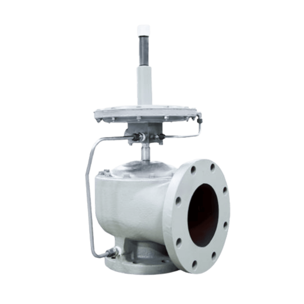
Pilot Operated Valves
BLANKETING AND RECOVERY
Tank Blanketing and Vapor Recovery
DISPLAYS
Ground Level Displays
Touch Panels
CALIBRATION TOOLS
Remote Calibration
Data Transmitters
Transmitters
INTERFACES, TERMINALS, AND COMMUNICATIONS
Remote Terminal Units, Field Interfaces, DAQs, and Protocol Converters
WASTEWATER & BIOGAS
Biogas Stream Equipment
Digester Cover Equipment
Waste Gas Burners and Flares
ENVIRONMENTAL MONITORING
Noise
Outdoor Sound Monitoring
Indoor Sound Monitoring
Dust
DM30 Dustsens
DM30N Sitesens
Storage Tank & Liquid Level
Crude Oil Solutions
Chemical Storage Solutions
Fuel Storage Solutions
STORAGE
Calibration, Display, and Interface Solutions
Dry Goods Solutions
Wastewater & Biogas
Digester Gas Storage, Transport & Flaring
Crude Oil Solutions
Storage Tank & Liquid Level
Inventory Control